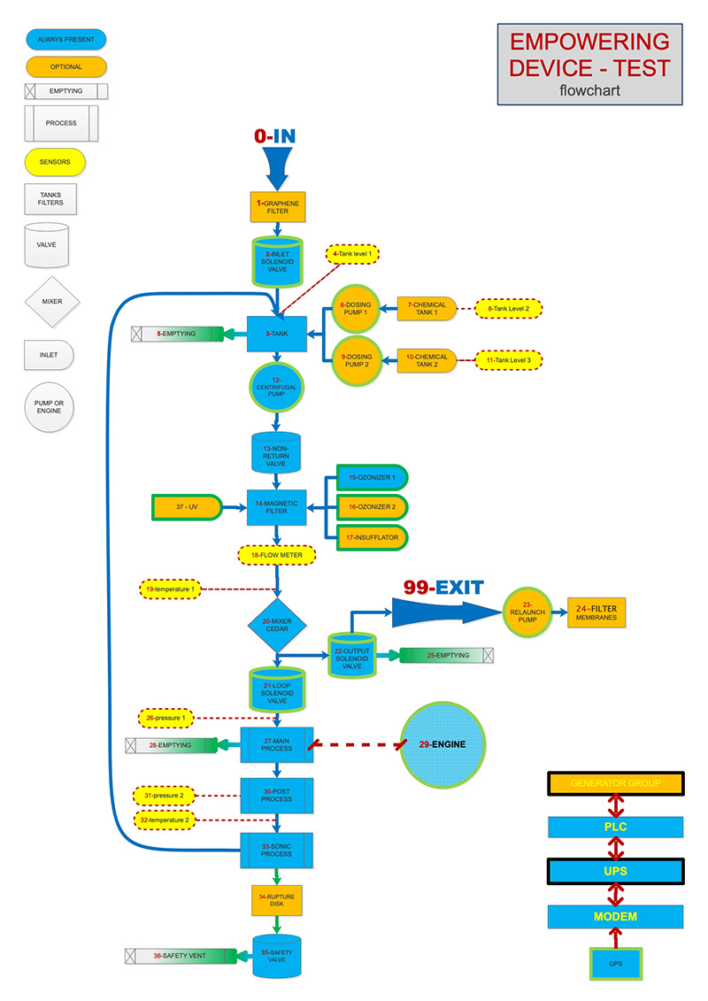
However, many of the processes we have developed are "on-line" kind: the machinery does not perform processing cycles but the liquid enters and exits without stopping, undergoing the treatments one after the other. In some cases we have provided for the presence of several cavitators one after the other to maximize the amount of liquid treated with the least use of electricity.
The fluid to be treated is introduced into the machinery through a flanged opening placed on the top (0). A graphene filter can optionally be positioned immediately before the flanged opening (1).
After the solenoid valve (2) which is placed immediately behind the inlet flange, a cannula guides the fluid towards the base of the tank (3) in such a way that the filling of the same takes place from the bottom upwards, exploiting the principle of communicating vessels, thus avoiding the formation of annoying turbulence that can trap air bubbles.
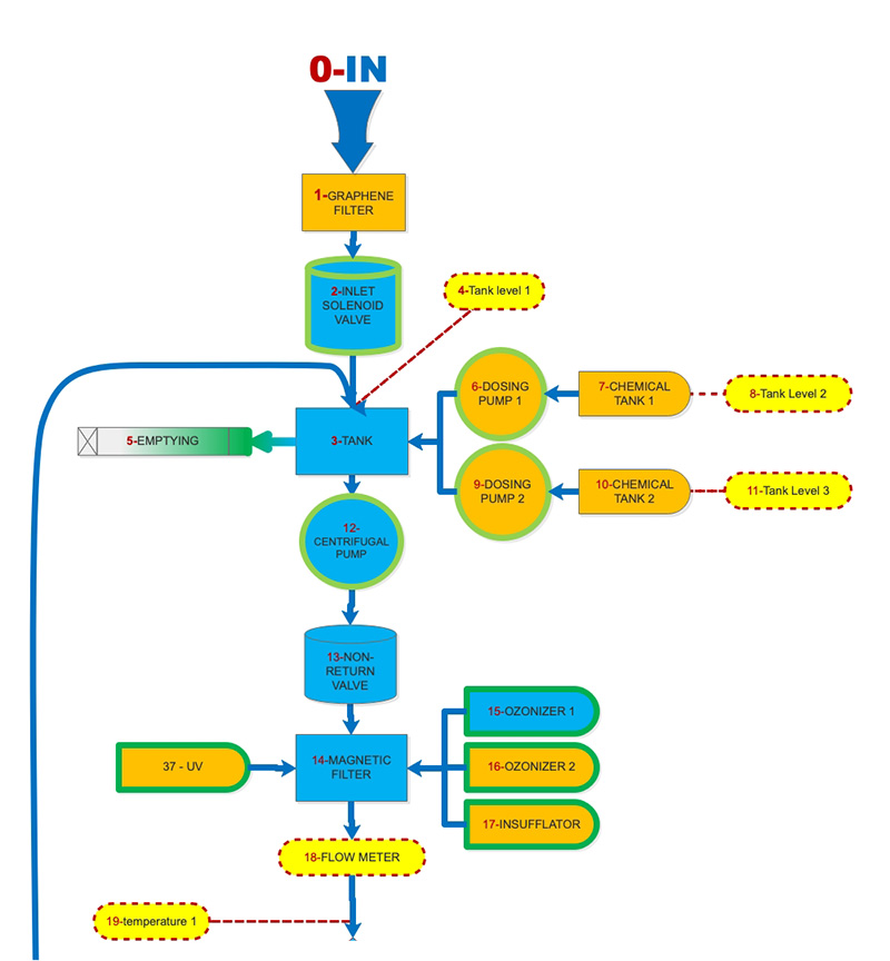
The inlet solenoid valve closes automatically when a preset level (4) for filling the tank is reached or upon manual command of the user or of the specific automatic processing program selected.
At the base of the tank there is a manual tap (5), accessible from the outside, to be used for taking samples and to facilitate complete emptying.
Optionally, up to two chemical tanks can be installed next to the loop tank, or one of double size, which can be filled from the outside equipped with level and dosing pump (6-7-8 & 9-10-11).
On the base of the tank, in a central position, a straight pipe leads to the centrifugal pump (12), and, immediately after, passes the non-return valve (13).
The pump re-launches the fluid towards the mixer also called CEDAR (20). In the piping between the mixer and the pump there are the magnetic filter (14), the flow meter (18), the first temperature sensor (19) as well as the inlet cannulas of the standard ozonator (15) of the second ozonizer (16) and an optional insufflator (17).
At the mixer outlet, the fluid can either continue the loop passing a special solenoid valve (21) or exit (99) from the machine passing another solenoid valve (22) beyond which one or more booster pumps (23) can be optionally placed as well as membrane filters (24). The outlet, being at the lowest point, is also used to empty the machinery (25) if it is necessary to clean it.
Beyond the valve that enters the loop, after the pressure control (26), the fluid enters the main process (27), which can be completely emptied by means of a special manual faucet (28) accessible from the outside, on which it is also connected the engine (29) of the device. At the outlet, the fluid passes into the post process (30) where both the temperature (32) and the pressure (31) are metered and from there into the sonic process (33) where the fluid undergoes the last treatments, observable through a porthole in glass, to then return to the tank.
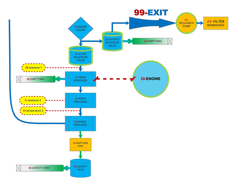
Exactly as it happened at the inlet of the liquid, a cannula guides the fluid towards the base of the tank in such a way that the filling of the same takes place from the bottom upwards, exploiting the principle of communicating vessels, thus avoiding the formation of annoying turbulence that can trap air bubbles.
In case of too high pressures, if present as options, the safety valve (35) or the rupture disk (34) will operate and convey the excess fluid to the outside through a safety vent (36).
A fan system draws air from the basement of the device to eject it from the sides of the same: up to 400 cubic meters of air per hour eventful guarantee a correct parts as well as the reduction in temperature in about 5 cubic meters of all content space inside the protective hood. An optional UV lamp set is placed before the cedar (37).